Making Pong for NES (Week 1)
Bear in mind:
- All I do may be completely and utterly wrong
- This post may contain strong language
- It’s not a tutorial. It’s just a documentation of my journey building this game with thorough explanation of what’s going on
- My english sucks, so be ready for poorly worded sentences, mistakes and misunderstandings
- By the way, don’t hesitate to tell me about my mistakes in the comments or through social media/email
Why?
Docendo discimus
or, if you’re not into summoning a demon much:
By teaching, we learn
Well, teaching is a strong word, more like trying to explain what the hell I’m doing, mostly to myself. And practicing english is good enough excuse to spend a week writing this.
Why NES/Famicom/Dendy?
I’ve always wanted to make a game for an old hardware1. Limit myself with a lightweight assembler, very small RAM/ROM and slow CPU. Squeeze all the juice this hardware has. Being sure it’s gonna run all my smelly code exactly the way I intended with same performance on every unit. And for all that, I chose NES.
Juice squeezing aside, let’s start with something simple, like Pong.
6502 assembler
Assembler is not as hard as you might think, especially 6502’s. Developing for NES doesn’t seem too difficult too. Sure, after writing 6502 assembly code, you really appreciate even simplest syntactic sugar. And still, it’s not too complicated and definitely not as frustrating, annoying and unsatisfying as coding for Android2 or setting up C++ project.
If you don’t know 6502 assembler, but still want to follow, check out this page for opcode descriptions or you can find some tutorials in Links section below.
But basic idea:
- You load some value in one of three registers (
LDA,LDX,LDY) - You manipulate this data (
INX- incrementXregister by one, for example) - You store resulting data (
STA,STX,STY) - And then branching, transfer between registers, subroutines and all that fun stuff
Or you can just read this post purely for it’s entertainment value, if you think it has one.
Tools
I’m going to use Windows, FCEUX emulator, NESst and nesasm3 assembler. Also, I grabbed nesdefs.asm and nesppu.asm from 8bitworkshop3 and ported it to nesasm4. This 2 files contains many useful constants and macros.
iNES Header
Every rom starts with a header, iNES header in our case:
  .inesprg 1   ; 1x 16KB PRG code
  .ineschr 1   ; 1x  8KB CHR data
  .inesmap 0   ; mapper 0 = NROM, no bank swapping
  .inesmir 1   ; background mirroring
So, here we have:
- 1 16kb PRG ROM - basically our game/engine code
- 1 8kb chr rom - our graphics data.
- No bank switching (32 kb PRG max)
- vertical background mirroring
For pong this configuration should be plenty.
Header is not really part of the rom and only used by emulators (and probably flash catridges).
Variables
16 bit variable for left paddle position looks like this:
paddle1PosLo .rs 1 ; low byte of the left paddle's position
paddle1PosHi .rs 1 ; high byte of the left paddle's position
Format: variable_name .rs n bytes
.rs - reserves n bytes of memory for this variable.
We can declare it as 1 variable with .rs 2 and then use LOW and HIGH syntax to access low and high byte.
We don’t really need low byte of the paddle’s position at this point, but we’re definitely gonna need it later for 16 bit movement calculations.
16 bit calculation will help us achieve smooth and nice motion.
Interrupts
Interrupts are something like hardware events. For example, user hits reset button, that triggers CPU interrupt and program counter jumps to your interrupt vector.
NES has 3 of those:
- NMI ($FFFA-$FFFB) or Non-Maskable Interrupt - called at the end of each frame (or at the start of vertical blanking)
- Reset ($FFFC-$FFFD) - called each time reset button is pressed (dah) or each time the program is started
- IRQ+BRK ($FFFE-$FFFF) - something we don’t need right now and I don’t honestly know exactly what it does at the moment. Don’t forget, my prior experience is a couple of weeks screwing around with emulator and reading some articles.
We declare interrupt vectors like this:
.macro NES_VECTORS
  .org $fffa		; start at address $fffa
  .dw NMIHandler	; $fffa vblank nmi
  .dw Reset		; $fffc reset
  .dw 0	; $fffe irq / brk
  .ENDM
Reset interrupt
Initilization
At this stage we need to disable PPU5, interrupts and decimal mode (NES CPU doesn’t support it anyway), set up stack pointer and more.
NES CPU (2A03) is a stripped down 6502 CPU, it lacks decimal mode, but has specific memory-mapped registers for I/O, sound, PPU, etc
  NES_INIT	; set up stack pointer, turn off PPU
  jsr WaitSync	; wait for VSYNC
  jsr ClearRAM	; clear RAM
  jsr WaitSync	; wait for VSYNC (and PPU warmup)
NES_INIT is a macro located in the nesdefs.asm file and can be included in the main file (pong.asm in my case) by writing .include "nesdefs.asm" at the start.
Here is what NES_INIT actually does:
  .macro NES_INIT
    sei	;disable IRQs
    cld	;decimal mode not supported
    ldx #$ff
    txs	;set up stack pointer
    inx	;increment X to 0
    stx PPU_MASK ;disable rendering
    stx DMC_FREQ ;disable DMC interrupts
    stx PPU_CTRL ;disable NMI interrupts
    bit PPU_STATUS ;clear VBL flag
    bit APU_CHAN_CTRL ;ack DMC IRQ bit 7 ; what?
    lda #$40
    sta APU_FRAME ;disable APU Frame IRQ
    lda #$0F
    sta APU_CHAN_CTRL ;disable DMC, enable/init other channels.
  .endm
VSYNC. We’re just checking if highest bit (bit 7) of PPU_STATUS ($2002) is 1.
WaitSync:
  bit PPU_STATUS ; triggers Negative CPU flag
  bpl WaitSync
  rts
Clear RAM. This is necessary, because we can not be sure what’s in the ram when reset interrupt is triggered. So we should always assume, that the content of the ram at reset is unusable garbage and may not be all 0’s as you might be expected.
ClearRAM:
  lda #0 ; A = 0
  tax ; X = 0
.clearRAM
  sta $0,x ; clear $0-$ff
  cpx #$fe ; last 2 bytes of stack?
  bcs .skipStack ; don't clear it
  sta $100,x ; clear $100-$1fd
.skipStack
  sta $200,x ; clear $200-$2ff
  sta $300,x ; clear $300-$3ff
  sta $400,x ; clear $400-$4ff
  sta $500,x ; clear $500-$5ff
  sta $600,x ; clear $600-$6ff
  sta $700,x ; clear $700-$7ff
  inx ; X = X + 1
  bne .clearRAM ; loop 256 times
  rts
And another VSYNC for a good measure.
Palettes
Next we need to tell NES where palette information is gonna be stored ($3F00).
  lda #$3f	; $3F -> A register
  ldy #$00	; $00 -> Y register
  sta PPU_ADDR	; write #HIGH byte first
  sty PPU_ADDR  ; $3F00 -> PPU address
In NES_INIT macro we disabled NMI and rendering, now, after we initialized palettes, it’s time to re-enable it.
  lda #CTRL_NMI
  sta PPU_CTRL	; enable NMI
  lda #MASK_COLOR
  sta PPU_MASK	; enable rendering
PPU_CTRL bits:
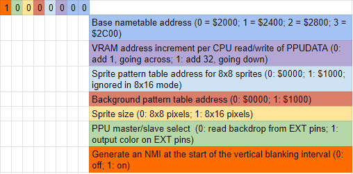
PPU_MASK bits:
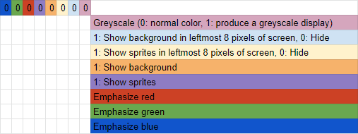
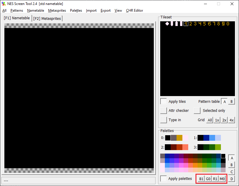
You can preview what grayscale and color emphasis would look like with your palette and sprites in NESst
You can include palettes as a binary file:
Pallete:
  incbin "palette.pal"
palette.pal is a simple binary file with no header or anything and contains palettes data:
$0f,$00,$28,$30,$0f,$01,$21,$31,$0f,$06,$16,$26,$0f,$09,$19,$29,
$0f,$00,$28,$30,$0f,$01,$21,$31,$0f,$06,$16,$26,$0f,$09,$19,$29
or just include binary data as a plain text:
Palette:
  .db $0f,$00,$28,$30,$0f,$01,$21,$31,$0f,$06,$16,$26,$0f,$09,$19,$29 ;;background
  .db $0f,$00,$28,$30,$0f,$01,$21,$31,$0f,$06,$16,$26,$0f,$09,$19,$29 ;;sprites
This numbers correspond to color from internal NES’ palette: 6
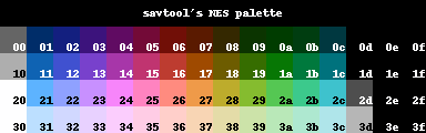
1 set of 4 palettes for background and 1 set for sprites.
In nesST you can click “Palettes” -> “Put to the clipboard” -> “ASM data” to copy a palette. Don’t forget, that only copies one palette set (16 colors) at a time.
Load palettes
LoadPalettes:
  lda PPU_STATUS ; read PPU status to reset the #HIGH/#LOW latch
  lda #$3F
  sta PPU_ADDR   ; write the #HIGH byte of $3F00 address
  lda #$00
  sta PPU_ADDR   ; write the #LOW byte of $3F00 address
  ldx #$00  ; start out at 0
LoadPalettesLoop:
  lda Palette, x  ; load data from address (palette + the value in x)
  sta PPU_DATA    ; write to PPU
  inx                   ; x += 1
  cpx #$20              ; Compare X to hex $20, decimal 32 (background + sprites palletes (4*4) * 2)
  bne LoadPalettesLoop  ; Branch to LoadPalettes loop if compare was Not Equal to zero
                        ; if compare was equal to 32, keep going down
Here we just copying our palette’s data to $3f00.
Remember how we set up location to store palette data earlier? Yes, it was $3f00
Sprites
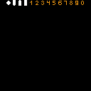
This is the first page (left side) of my chr rom:
Loading sprites
  lda #$00
  sta OAM_ADDR ; set the #LOW byte (00) of the RAM address
  lda #$02
  sta OAM_DMA  ; set the #HIGH byte (02) of the RAM address, start the transfer
Writing $0200 to OAM RAM address.
$0200-$02FF now will contain copy of OAM (64 entries).
This macro will simplify sprite loading routine:
graphics.asm
;; \1 sprites W/ offsets \2 offset \3 sprites count
LoadSprites .macro
  ldx #$00
LoadSpritesLoop\@:
  lda \1, x
  sta OAM_RAM+\2, x
  inx
  cpx \3
  bne LoadSpritesLoop\@
  .endm
\@ - Special parameter that returns a different number for each macro.
\1-\3 - input parameters.
In C it would’ve looked something like this:
void LoadSprites(byte sprites, byte offset, byte spritesCount) { ... };
So, we are loading our metasprite data (sprites) into OAM_RAM with offset
while X not equal to length of metasprite (sprites count)
Calling this macro:
LoadSprites MiddlePadle, #$00, #$10
By the way, only now I noticed that I call paddle’s metasprite - “MiddlePadle”. Don’t pay much attention, I wanted to make 3 differently sized paddles, as power-ups, so…
Maybe we’ll do
Here is what MiddlePaddle metasprite looks like:
MiddlePadle:
  .db 0,  $03, $00, $00
  .db 8,  $04, $00, $00
  .db 16, $04, $00, $00
  .db 24, $02, $00, $00
Just a reminder.
To indicate numeral system, you can prefix number with:
% - binary
$ - hex
no prefix - decimal.
Let’s examine first row:
  ;vert sprite attr horiz
  .db 0, $03, $00, $00
-
First byte is
yscreen coordinate. -
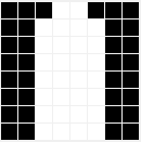
Second byte - sprite index. In our .chr file $03 corresponds to this sprite.
- Third byte is attributes 7
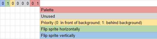
Two least significant bits are palette number. 00 - first palette set, 01 - second, 10 - third, 11 - fourth. So, 0-3 in binary. Pretty straightforward.
- Fourth byte is
xscreen coordinate.
In our case both x and y screen coordinates not absolute, but relative. So, 0 is not an y position, but an offset of y coordinate. We offset each sprite by 8 (decimal), on account of using 8x8 pixels sprites.8
Since we have 2 paddles (right and left), it’s a good idea to use offsets, so we can re-use same metasprite information for both paddles.
Initialize variables. $80 - is a middle of the screen.
  lda #$80
  sta paddle1PosHi
  lda #$00
  sta paddle1PosLo
Now, all it’s left is wait for NMI interrupt.
.endless
  jmp .endless	; endless loop
NMI
PPU clean up
Next step - prepare PPU to render next frame. And there is OAM decay, so you should update OAM content each frame. 7
Plus, at this point we can enable sprites by writing 1 in 4th most significant bit to PPU_MASK.
  lda #$00
  sta OAM_ADDR       ; set the #LOW byte (00) of the RAM address
  lda #$02
  sta OAM_DMA       ; set the #HIGH byte (02) of the RAM address, start the transfer

  ;;This is the PPU clean up section, so rendering the next frame starts properly.
  lda #%10000000   ; enable NMI
  sta PPU_CTRL
  lda #%00010000   ; enable sprites
  sta PPU_MASK
  lda #$00        ;;tell the ppu there is no background scrolling
  sta $2005
  sta $2005
Position update
Now we only need to update paddle’s position and tell PPU to draw it on screen in this new position.
Although we are not changing paddle’s position now, this function will be helpful later
This next macro just adds current position of a paddle and offset to form a paddle’s metasprite.
transform.asm
;; \1 posYHi \2 posXHi \3 offset
UpdatePos  .macro
  ldx #$03
  ldy #$00
  UpdatePosLoop\@:
    lda \1
    clc
    adc MiddlePadle, y ; add high byte of current y position to y offset (first byte of paddle's OAM ROM)
    sta OAM_RAM+\3, y ; store it in OAM RAM with offset
    lda \2 ; x position is constant for paddle
    sta OAM_RAM+\3, x

    inx
    inx
    inx
    inx

    iny
    iny
    iny
    iny

  cpy #$10 ; you can live it as constant or make it fourth argument
  bne UpdatePosLoop\@
  .endm
And we call it like this:
UpdatePos paddle1PosHi, #$0C, #$00
You probably noticed 4 inx and iny instructions in a row and thought it looks stupid. Yeah, well, it does, but it’s not really that stupid if you think about it.
You could’ve wrote like this instead:
  txa ; 2 cycles
  clc ; 2 cycles
  adc 4 ; 2 cycles
  tax ; 2 cycles
So, 4 instructions, 8 cycles. Same as just calling inx 4 times. See? It’s not stupid, it’s maybe lazy, but quite efficient.
Metasprite
Let’s look at our middle paddle’s OAM ROM again:
MiddlePadle:
  .db 0,  $03, $00, $00
  .db 8,  $04, $00, $00
  .db 16, $04, $00, $00
  .db 24, $02, $00, $00
Each sprite only 8x8 pixels. Mario, for example, is a bit bigger, than that. Especially, well, big Mario.
To form a big Mario’s metasprite you need to combine a few sprites.
Look at this Gif:
![]()
And same with our paddle. Pay close attention to x and y offsets, sprite index and attributes.
![]()
And don’t forget to put return from interrupt (RTI) opcode at the end.
8bitworkshop uses SAVE_REGS and RESTORE_REGS at the start and the end of NMI respectively. I don’t really know why it’s necessary.
This macros pushing registers to stack (SAVE) and pulling registers from stack (RESTORE). You can find macros’ code in nesdefs.asm
Memory mapping
Couple of words about memory mapping and how we handle it right now.
In iNES header we declared 1 prg rom (2 banks, each 8 kb, 16kb in total) and 1 chr rom (1 bank, 8 kb in total). You probably already noticed, every bank exactly 8 kb in size.
PRG can be accessed through CPU memory addresses $8000 - $FFF9.
Look at this image by BunnyBoy:
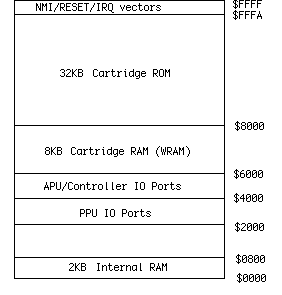
So, we put our PRG rom data in the first half of 32 kb reserved for cartridge rom - first bank in $8000, second in $A000.
You should use a mapper, if you need more than 32kb of PRG
CHR rom connected to PPU and copy of chr rom stored in memory addresses $0000-$2000.
And you guessed it - it’s bank 3.
- In first bank we store all
ResetandNMIcode - In second bank - palette data and pattern tables (our MiddlePaddle OAM ROM data)
- In third - our pong.chr
In code it looks something like this:
  .bank 0
  .org $8000 ;first 8 kb of prg
Reset:
  NES_INIT	; set up stack pointer, turn off PPU
  jsr WaitSync	; wait for VSYNC
  jsr ClearRAM	; clear RAM
  jsr WaitSync	; wait for VSYNC (and PPU warmup)

  ...
Don’t think about it too hard for now. We’re gonna explore memory mapping and, well, mappers later. Probably. Maybe.
Result
And after all your blood, toil, tears and sweat, if the Moon is in right state and you well-behaved all year, you’ll see
Drumroll, please

A lot of work to display 32x8 pixels metasprite on empty 256x224 pixels screen. But I don’t know about you, for me it’s still satisfying as hell.
Links
You can find a source code here: github
Some related links:
- Thanks to @cppchriscpp we now have a mirror of great tutorial series Nerdy Nights. Highly recommended.
- 8bitworkshop
- Great video series about 6502 by Ben Eater
- Tons of useful information about 6502 6502.org
- Tons of useful information about NES nesdev
-
I mean, famicom already 36 years old. Holy shit ↩
-
Just kidding, chill ↩
-
By the way, great online IDE for 6502 assembler/cc65 with emulators of many 8 bit systems, contains some useful tools, syntax highlighting, etc. If you’re OK with online IDE’s, definitely check it out. ↩
-
I only ported some code, that I’m gonna use in this game. So, it’s not a full port. ↩
-
PPU or Picture Processing Unit - rtx2080 in the 8 bit world. More like adreno to be exact, since it’s a video chip and not a video card ↩
-
By 8, don’t screw up like I did. If you offset
xand/oryonly by 1, you’ll have a lot of problems, including problems with sprite priority. I know it’s sound obvious, but I managed to overlook it at first ↩